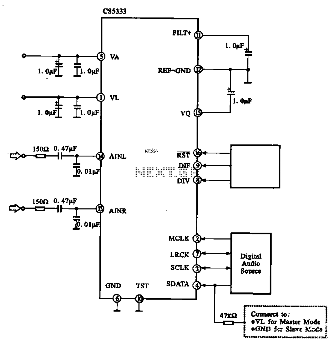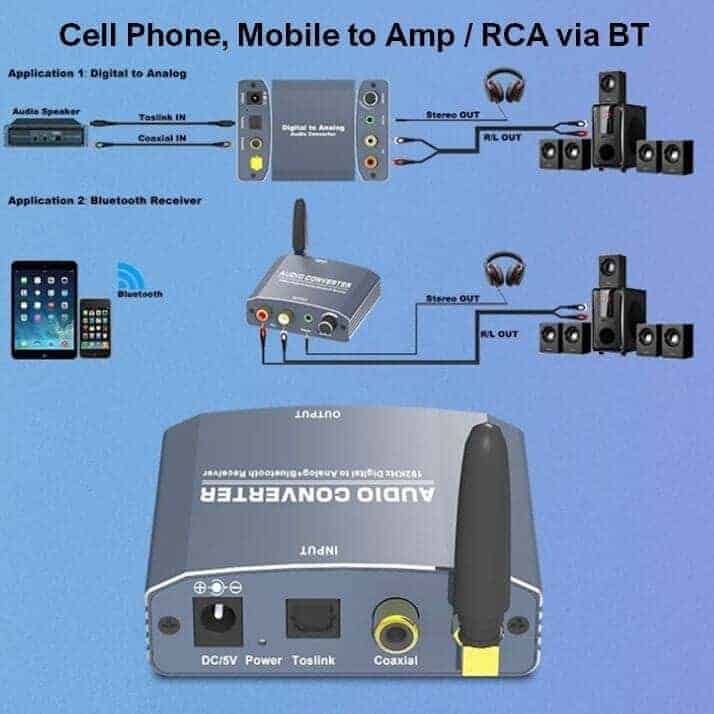
- DIGITAL TO ANALOG AUDIO CONVERTER CIRCUIT DIAGRAM HOW TO
- DIGITAL TO ANALOG AUDIO CONVERTER CIRCUIT DIAGRAM FULL
- DIGITAL TO ANALOG AUDIO CONVERTER CIRCUIT DIAGRAM CODE
- DIGITAL TO ANALOG AUDIO CONVERTER CIRCUIT DIAGRAM SERIES
(This is called “dynamic range.”) For instance, the sound level from a symphony orchestra varies from about 40dB to 130dB. Thus, to get 10 bit accuracy we would need a 14 bit converter.Įven if the maximum amplitude of our signal matches the full-scale value of the converter, the signal amplitude is likely to vary significantly over time. Typically, we might have a margin of over a factor of ten perhaps 4 bits. It is uncommon for the signal amplitude to exactly match the full-scale value of the converter. What then is the point of going to higher resolution? Higher resolution provides greater range. It is rare that we would need precisions better than 1 part in 1000, or 10 bits. Thus, for 8 bits (the number of bits in a typical low end converter) there are 256 levels, while for 24 bits (the maximum common converter resolution) there are 16,777,216 levels. In base 2, the number of levels that can be represented by an n bit sample is 2^ n. The number of bits available to represent each sample is called the resolution. How accurate is the representation? There are two basic limits on the accuracy, resolution and sampling rate.

If we then use the samples to represent the signal, we get the signal in the lower plot, where the points are joined by the dashed line. The curve in upper plot of the graph below represents a signal to be sampled. We can better visualize sample tables with a graph. Thus, to represent a time-varying signal, we build up a table of the value of the signal as a function of time, for example: Real-world signals are continuous in time as well as level. Both are important DACs are used to control experiments, while ADCs are used to read data from experiments. Devices that change a signal the other way, from digital to analog, are called digital to analog converters (DAC). Devices that change an analog signal to a digital signal are called analog to digital converters (ADC). Since the real world is analog, but the computer world is binary, we need to be able to convert signals between the two. Non-integer numbers are represented by multiplying in an appended exponent thus, the more bits, the greater the precision of the number.Įight bits taken together constitute a byte, and computers are typically organized around byte processing, not bit processing. The more bits used, the larger the integer number that can be represented.
DIGITAL TO ANALOG AUDIO CONVERTER CIRCUIT DIAGRAM SERIES
Where the are the series of bits used to represent the number. Numbers are decoded using a power series in 2: The digits in a base 2 number are called bits, thus, a typical number in base 2 number is a collection of bits like 01011010.

If a 0, or off state, is represented by a voltage near 0, and a 1, or on state is represented by a voltage near 4 (a scheme used by a common family of digital devices called TTL logic), then noise is unlikely to cause a fluctuation great enough to confuse the two.īecause computers can only represent two states, numbers are stored in binary, or base 2. This so-called digital representation of information has many advantages over analog representations, most importantly that digital information is relatively immune to noise. Internally, however, modern computers deal only with discrete quantities specifically, they deal only with quantities take on only two values: on or off. But even measurements of discrete phenomena tend to be confounded by noise and produce continuous data. There are, of course, intrinsically discrete exceptions to this rule, like the quantization of charge or the quantum hall effect. Our world is largely analog and continuous quantities vary smoothly.
DIGITAL TO ANALOG AUDIO CONVERTER CIRCUIT DIAGRAM FULL
Assuming that the DAQ digital output high level is exactly 5V, what is the full scale value (largest output) of the DAC in this exercise? Given the DAC in Exercise 10.2 has a resolution of 5 bits, how close to their ideal values must each resistor be?Ģ.
DIGITAL TO ANALOG AUDIO CONVERTER CIRCUIT DIAGRAM HOW TO
DIGITAL TO ANALOG AUDIO CONVERTER CIRCUIT DIAGRAM CODE
Two versions of the programs are typically available for download: an executable version that should run without LabVIEW (but requires a large download from National Instruments, which should occur automatically, and only needs to be done once) and should run on PC’s, Mac’s and Linux boxes and the original LabVIEW source code which requires LabVIEW.īefore coming to class complete this list of tasks:

Many of these programs can be downloaded from the 111lab\BSC Share\ on the U: Drive from the 111-Lab computers. Several LabVIEW programs are mentioned in this lab writeup.

In this lab you will learn how to convert data between analog and digital, and the many pitfalls in doing so.


 0 kommentar(er)
